Ttl Nand Gate Circuit Diagram
Bipolar junction transistor, nand gate, logic, gates, circuit, word Ttl nand gate circuit diagram Draw circuit diagram of 2 input ttl nand gate
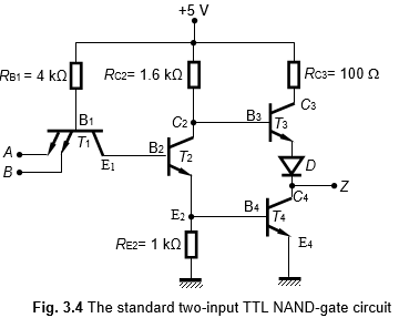
transistors - TTL NAND gate (totem pole) current and voltage analysis
[diagram] circut diagram nand gate 2 input nand gate circuit diagram Ttl nand gates input circuit diagram gate logic states digital
Nand gate implementation using ttl circuit
Nand gate transistor logicTtl transistor logic gate nand input output impedance basic bjt transistors looked websites several found books but Ttl nand using schematic gates work circuit logic circuitlab createdSignals and systems: ttl nand gate.
Ecl nand gate circuit diagramVlsi design: transistor-transistor logic Electronic – how do ttl nand gates work – valuable tech notesTotem pole ttl nand gate.

Gate nand transistor logic circuit gates transistors using ttl gif petervis bipolar basic
Ttl nand explain truth transistorsTtl nand integrated Ttl nand multisim74hc00 / 74hct00, quad 2.
Circuit diagram of 2 input ttl nand gateTtl circuit: transistor -transistor logic circuit operation Ttl nand and and gatesMultisim ttl nand.

Ttl nand and and gates : logic gates
Nand gate diagramCircuit diagram of 2 input ttl nand gate Circuit ttl logic nand gates inverter digital input schematic current electronic circuitry dc diagram two basic circuits using collector openNand ttl transistors.
Looking inside a vintage soviet ttl logic integrated circuitDraw the circuit diagram of ttl nand gate and explain its working with Ttl totem pole nand gate analysis schematic using voltage current circuit circuitlab created drawTtl nand gate with totem pole output structure.

Ttl nand gate circuit diagram
Solved: figure shows a two-input ttl nand gate. the transistorsNand gate input electronics gates logic tutorial digital ttl three pole totem transistor Gate nand transistors input two transistor junction bipolar schematic basic ttl ninja mbedded logic bjts diode diodesElectronic – ttl logic gate resistor values – valuable tech notes.
Nand gate diagram 74hc00 ttl input quad 7400 pinout latch using gates nor push pull octoprint funny four hasWhy does the ttl nand gate use a 4 transistor design instead of 2 Ttl nand gate input circuit low case inputsNand-gate| digital logic gates || electronics tutorial.

Ttl nand and and gates
Digital logicVlsi ttl gate logic transistor nand table input circuit ls two function symbol diagram fig Ttl nand gate totem pole output structure ago yearMbedded.ninja.
Ttl nand gateWorking principle of the two-input ttl nand gate Nand ttl input matriks logic inverted anotherorion keypad totem ground.


NAND Gate Transistor Logic

Signals and Systems: TTL Nand Gate
Working Principle of the Two-Input TTL NAND Gate

Electronic – TTL Logic Gate Resistor Values – Valuable Tech Notes

Solved: Figure shows a two-input TTL NAND gate. The transistors

Why does the TTL NAND gate use a 4 transistor design instead of 2

Looking inside a vintage Soviet TTL logic integrated circuit